| Gyro Erection Limitations | |||||||||||
|
|||||||||||
| Normal Gyro Erection Functions | |||||||||||
|
|||||||||||
The gyro rotor is typically 1 kg mass spooled up to a speed of about 25,000 RPM for a very high gyroscopic inertia. An electric motor is used in the Collins and Aim units above. In the Honeywell-King vacuum driven unit an airflow of about 1 cubic ft/min is used to spool up the internal air turbine. This air exits the gyro housing through 4 ported holes. When the gyro is exactly vertical and in level flight the control vanes equally cover the 4 ports and the reaction forces on the gyroscope are precisely balanced. When any drift or deviation is encountered, a pair of ports will become unequally covered and the asymmetric airflow causes a precession of the gyro back to the correct alignment with the earth. The rate of this control is rather slow - about 3 degrees per minute. This is a number worth memorizing for it repeats in many places, like the rate a DG corrects after turns. |
|||||||||||
| Normal Start-Up Operations | |||||||||||
| Vacuum Panel Horizon Gyros. When the engines start and vacuum is available, the gyro air flow quickly
is full spec airflow. The turning rotor slowly builds up speed and gyroscopic
inertia increases. At the beginning the ports are unequal and the resultant
air force causes large precessional forces with the characteristic large oscillations of the gyro horizon
display. As the RPMs increase, the control forces are the same, but are
pushing against the much larger gyroscopic enertial forces, so the oscillation
becomes less as the unit comes to equilibrium at the correct vertical presentation.
A well calibrated unit always shows this "nutation" for the first
half minute. A poorly calibrated unit or one with sticky bearings will
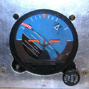
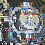
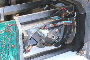
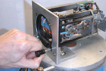
simply slowly erect to operating attitude. Electric Remote Vertical Gyros. These units behave the same as a vacuum panel gyro at the start. This is because the electric switches and electric force motors have a similarly greater effect when the electric rotor motor is at the lower initial speed on start-up. Electric Panel Horizon Gyros. These units are the opposite of the other two types. There is almost no erection force in the first minutes of operation. The source of erection force is air from a centrifugal fan mounted on the internal electric rotor which is not turning fast enough to move much air during startup. The airflow of full rpm is the amount for slow erection. There is NO FAST erection system except the knob on front. In the photos below left, typical attitude is shown for an electric horizon in startup. Notice the 45 degree pitch and roll over and also that the erection ports are fully open. A newly overhauled unit is usually so well balanced that it will actually start itself up correctly on this very minimal airflow, but NONE are certified to do so. Crew should as soon as convenient after electric power up pull out the erection knob (photo below right) firmly and slowly and completely (taking 15-20 seconds). Damage will be done if it is pulled out too quickly and more likely if the unit is a full normal operating speed. The gyro is designed to maintain the correct attitude itself thereafter. Only electric panel gyros have these necessary manual erection systems. |
|||||||||||
|
|||||||||||
Startup and Spooldown Times |
|||||||||||
| Vacuum Panel Horizon Gyros. The time for a vacuum gyro horizon to get to operational speed is short
- 2 to 4 minutes. The grease in vacuum driven gyros is thinner than that
in electric gyros so they speed up faster, and spool down longer. When
vacuum is first applied, it should oscillate wildly in pitch and roll at
about 3 Hz. It should arrive within a few degrees of vertical within 10-20
seconds and stop oscillating (nutation) in 20-30 seconds. Any last slow
erection corrections will be at the 3 degrees per minute rate. It will
thereafter maintain the attitude. When the units are freshly overhauled
it takes only 3-5 minutes for them to coast to a stop. As the bearings wear in, the stopping time will be typically in the 8-10 minute area for a half time gyro. As the unit nears the end of its service cycle life (2000-3000 hours) the grease is gone from the bearings and they are running dry. It will now take from 15-20 minutes to come to a stop. Then the bearings start to flake, chip and ruin. In consequence it takes less and less time for the rotor to stop. A unit on its last legs will again only take 5 minutes to stop. If you listen to it, it will sound just terrible. It is not unusual for such bad rotor bearings at this stage, to lock up sometimes and not let the gyro get started, or in the coast down time to suddenly grab and cause the gyro to topple and spin - usually with destructive consequences and a noisy spectacular death! Electric Remote Vertical Gyros. The electric motors in these units will have reached full speed in 4 - 6 minutes in a freshly overhauled unit. They have valid indicators or gyro flags on the flight directors and the flags will lift when the motors have reached 80-90% full speed. As the bearings wear in there will be less friction and the flags will lift in 3 - 4 minutes. The same life cycle described above pertains to these bearings and times will get longer and longer for spooldown until their life's end when the time gets short again and they seize. Electric Panel Horizon Gyros. These units are subject to the same physics as the above 2 kinds, being physically similar to the vacuum panel units, but having the same grease type as the electric remotes. Since the electric motors run hot, they must have a heat tolerant grease, and so there are some small differences. See also section below on cold weather behaviours. Some flags on these units are intelligent circuits monitoring the rotor speed and are as described above. Other units have flags that have nothing at all to do with operational status but only tell you power is applied. |
|||||||||||
Cold Weather Considerations |
|||||||||||
| If the aircraft is cold soaked - as in being outside at sub-zero temperatures
overnight - and if electric space heaters are not provided - the grease
in the gyro rotor bearings gets very stiff. There are many variables here,
but the startup times may be expected to double or triple. In severe cases,
the unit may not be able to get started at all. This depends upon the source
of air for a vacuum gyro. If the inlet filter is outside the cockpit then
the rotor will stay cold. If the inlet filter is inside the cockpit, the
rotor will eventually be warmed up and start to work, but the erection
system won't work properly of course either for perhaps 30-40 minutes. In the case of electric gyros, panel or remote, the main behaviour is that they work but very much more slowly than usual. The grease in their rotors is stiff and the unit won't turn at the start either. But the electricity is flowing through the windings of the rotor/motor and will heat it up. In about 15-20 minutes there is enough heat to let the rotor/motor start turning. Sperry C-14 and VG-14 units in -30ºC overnight conditions can take about 20-30 minutes to lift the flags. There is NO SPEC from any manufacturer on operation in the cold from being cold. The ONLY spec is that electric units (like Honeywell Sperry) are specified after being in warm hangars to OPERATE in the cold (as in an unheated radio bay at 30,000 feet and -40ºC. The motors are low torque and only minor damage occurs - to the brushes (higher current) and bearings (more brinneling forces) occurs. A winters worth of such operations might reduce the service life by half. It is certainly worth installing space heaters for the gyros if you park outside for extended periods from time to time. A fair operational parallel is the engine. If the engine can be depended upon to start without special provisions after the suspected parking interval, the gyros will have no particular problem. But If you would muffle and protect the engine, remove its battery, plug in heaters, or get Herman Nelson to help, then best to have equal provisioning for the gyros. The change of the time to normal erection from normal warm hangar storage to this outside parking issue, is enough of a guide to judge this. Twice the time is about the limit. |
|||||||||||
Normal Shut Down Operation |
|||||||||||
| When the engines and the vacuum stop, and when the electricity is turned
off, the erection system no longer functions. Normal drifting factors together
with the dissipation of braking rotor energy around the axis of rotation
necessarily results in precessional force and a slow toppling action. The gyro will slowly drift off vertical
both in pitch and roll. It will take 5 minutes to stop when freshly overhauled.
It will take as much as 20 minutes at the end of its service life to come
to a stop. |
|||||||||||
| IT IS IMPORTANT THE AIRCRAFT (OR UNIT) NOT BE MOVED DURING THIS SPOOL-DOWN PERIOD. | |||||||||||
Such a turning or bumping can precipitate a violent toppling and/or motoring of the whole mechanism. At the least the centrifugal forces of this will change the calibration. At the worst the force is quite capable of breaking off parts. The Honeywell-King Service Memo 377 on the KI256 stresses the importance of not moving the aircraft for 15 minutes after the engine is powered down. Jet Service Letter SL-35A recommends 20 minutes. Most vertical gyros have solenoid brakes or thermal devices to prevent this destruction. In any event without electric power the flight director will not show the vertical gyro's behaviour. But it is still good practice to wait till gyros stop. |
|||||||||||
| False Start Behaviors - A "Toppling" that causes crew to not trust gyro. | |||||||||||
| If before the gyro has come to a complete stop, the electricity or vacuum
is reapplied, correct erection will not occur. Aviation gyroscopes must
"cold start" for correct performance. The most frequent ways
this occurs are: 1. An aircraft is preflighted including the warming up of the engines. It is then shut down. Fueling, and loading of passengers takes place. Engines are restarted. Less than the 5 to 20 minutes mentioned above has passed. The gyro is toppled. Looks like a critical failure. 2. An aircraft with an electric vertical gyro is preflighted in the hangar. Then it is shut down and tractored outside - usually turned 90 degrees in the process. Then passengers board and engines are started. Less the the 5 to 20 minutes has passed. The flight director is toppled. Looks like a critical failure. 2. An aircraft lands at an uncontrolled airstrip. It shuts off the engines and deplanes passengers and mail. New passengers climb aboard. Engines restart. Less than the 5 to 20 minutes mentioned above has passed. The gyro is toppled. Looks like a critical failure. Since the gyro rotor was still spinning it had considerable gyroscopic inertia remaining. When the airflow restored the port erection control the gyro begins to return to the correct vertical position, but the force to do so is low relative to this remaining inertia. The rate of return will quickly become the specified slow erection rate of 3 degrees a minute. If as an example, the display was 90 degrees sideways, it will take 30 minutes to arrive at the correct vertical position. These behaviours are a result of happenings on the ground, but the displacement of the display may not be severe enough to notice in the course of takeoff, especially if it is daytime VFR conditions, and the partially toppled display may not be noticed until the aircraft is climbing out or is settling out on course. It is thus often believed that the gyro has "toppled in flight". Actual toppling in flight can happen only if certain gyroscopic conditions prevail. Loss of power (vacuum or electricity) is the commonest reason. If the unit has gone dead and is not being correctly controlled, the erection is inop and it will either be spooling down and drifting or possibly completely non-moving. Pinched lines, case leaks, cases leaks when aircraft pressurize, internal failure of chokes and lines to supply rotor, installation of rotor backwards, bad or failing bearings, cold stiff bearing grease - all can stop a vacuum gyro. Intermittent wiring or connectors can fail the electricity supply to the other types. Loose internal parts or parts that have shifted can cause instability and toppling as well. One fault can lead to another. A unit can topple or spin by being moved into the hangar before the gyros have spooled down and this severe spinning cause an internal shift of calibration weights of the gyro. Thereafter it will be assymetric and unstable, or from an operational point of view appear intermittent. But the true cause is lost. If for a variety of possible faults it exceeds 180 degrees of drift in either pitch or roll, it will commence a violent spinning until the rotor finally stops. If the unit is drifting off to the side as a normal part of spool-down after shut-down and the aircraft is moved, the centrifugal forces on the gyro capsule so positioned will cause large precessional displacements - possibly enough to induce such a toppling destructive spinning. |
|||||||||||
| False Start "Toppling" - what to do. | |||||||||||
| Electric Vertical Gyro. There is a "Fast Erect Switch" always provided on the panel
for this exact purpose. Many crew are unaware of it. Be familiar with it.
Activating this switch causes a fast erect sequence and will erect the
working gyro to correct attitude in a couple of minutes. Electric Panel Horizon Gyro. Use the provided erection knob on the unit. Pull firmly, slowly, fully - taking about 15-20 seconds. Please don't put your boots on panel and pull. Vacuum Panel Horizon Gyro. Choice One. Shut down and wait for full stop of gyro and start again. It will be OK. If you are impatient take a pen or screwdriver putting it to the glass of the horizon gyro and to the bone immediately behind your ear. You will hear the bearings spinning and be able to tell when it stops for sure. Choice Two. Estimate the angle from vertical and divide by 3. The gyro will be correctly erected in that many minutes. Perhaps it is easier to wait that long. Perhaps the weather is VFR and you don't need the gyro for IFR flight and being OK in a short while is acceptable. |
|||||||||||
| False In-Flight "Topple" | |||||||||||
| There is yet another limitation of mechanical gyros that can occur and
cause loss of confidence in the system. All gyros are certified for a very
limited range of accelerations and attitudes. For absolute certain this
means all IFR procedures and all standard rate turns and all standard manoevers.
But unusual attitudes or poorly coordinated turns can topple gyros and the units are NOT specified to function correctly in these environments. Examples of such gyro toppling. 1. Aircraft is on test flight. No passengers. Little fuel. Little time. Having fun. Extreme turns are made. DG's or VG's are discovered to be suddenly way off the mark. 2. Aircraft is on ground with engines running either taxing or carrying out ground tests like engine runs or compass swings. Since turning around the yaw axis is not "coordinated" the gyros see considerable precessional forces during these motions, and may well precess or skip to an incorrect display and take the usual 3 degrees a minute to return to the correct settings. 3. Aircraft is on apron ready for take-off and is requested to hurry take-off for other traffic. Crew lift brakes and do wheelie turning takeoff. The rapid yaw acceleration can topple both the VG and DG. They will recover in the usual time. The error is usually noticed on climb out and causes deep concern. 4. Aircraft is orbiting in a constant turning at steep angles and possibly with power changes making thrust acceleration changes. After the manoever, the presentation has drifted from true verticality. Surveillance aircraft and helicopters often experience this. |
|||||||||||
| Operational Check for 100% Confidence. | |||||||||||
All gyro horizons are specified for this standard behavior. That they maintain earth allignment within 1 degree of pitch and roll during standard rate turns. This then is a flight test for 100% confidence that the system is trustworthy or is bad. Starting in level flight with a correct in-flight presentation make a standard 2 minute turn to the right. Coming out of the turn, the presentation must not be more or less than 1 degree in both pitch and roll to the truth. Then repeat this action to the left. Again, after a standard rate 2 minute turn, the aircraft should level out and find the display to be within 1 degree of the truth both in pitch and in roll. Any failure of this means the unit or the aircraft electrics or vacuum is miscalibrated or difficient. If the presentation is correct during and after the turning test, the system is sound, and the highest probability is the snag relates to one of these design limitation issues. |
|||||||||||
|
|||||||||||
| Terms and References | |||||||||||
| Topple - Note about the term. In this paper we use the practical aviation meaning.
Practically in aviation, "topple" means "the VG presentation is wrong - the system is not alligned with
the earth - the VG is not vertical". Strictly, the word "topple" in gyro physics refers to a gyro that has exceeded its the range of stable
operations and the gimble assembly is spinning, making any use of the gyro
useless. The word "spinning" is practically used for the unstable behaviour gyro people mean by "topple". Precession - Note about the term. All gyros precess. "Precession" is the rotation about one axis when a torque is applied about a perpendicular axis. Gyros are balanced as truly as possible to minimize precession. Then it is calibrated for specific precessional behaviours. For example the earth is always turning and so gyros must be made to precess at a rate equal to the earth's turning so that the display appears always to be alligned with the earth. Further, normal gyro erection control systems - slow, and fast if provided - use precession physics to keep the gyro's earth allignment true. In practical aviation "precession" is sometimes used to mean "the DG is not where it belongs". The correct and more common word for this is "drift". Honeywell Service Memo 377. Transportation and Handling of the KI 256 Flight Command Indicator and the KG 258 Horizon Gyro. L3-BF Goodrich-Jet Service Letter. SL-10J. Gyro Handling, Storage and Packaging. L3-BF Goodrich-Jet Service Letter. SL-35A. Vertical Gyros. Clarification of Operating Procedures and Erection Indications. L3-BF Goodrich-Jet Service Letter. SL-12C. Self Contained Attitude Indicator Operation - AI-804 and AI-904 Emergency Attitude Indicators. . |
|||||||||||
| General Note. To keep this paper brief and basic (yes really), some of the statements may be suffer precision. If any issues arise, please bring them forward, as corrections, additions or questions. Just e-mail me. jmctavish@westernavionics.com Jock McTavish. 4 Dec 03. | |||||||||||